Hardware and Environment Setup
Hardware Requirements
Development Board
The following Intel FPGA platforms are tested with XploR Studio IDE:
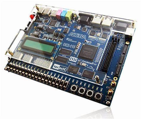
- Intel FPGA DE2-115 development board
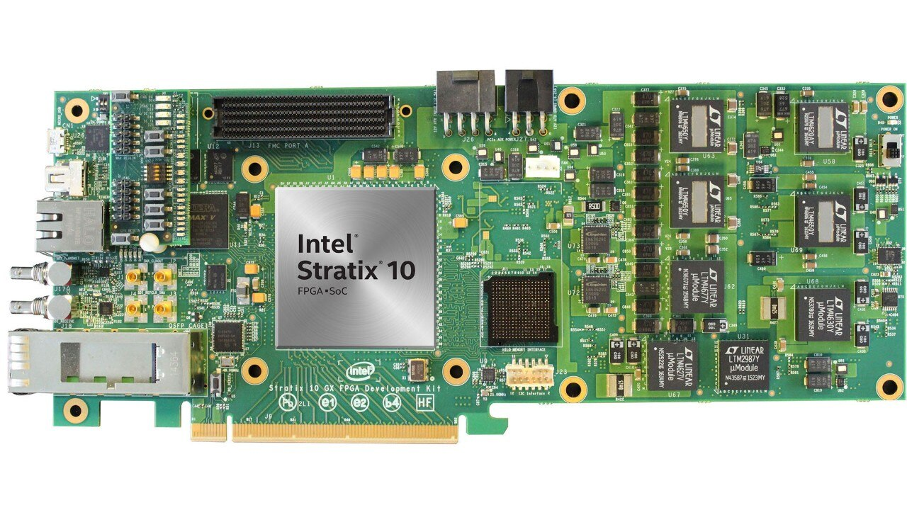
- Intel Stratix 10 GX board
USB RS232 adapter
The following USB-RS232 adapters are tested:
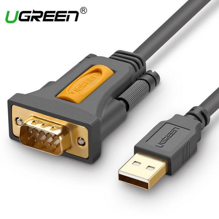
- UGreen USB-RS232 adapter
USB Ethernet adapter (optional)
The following USB-Ethernet adapters are tested:
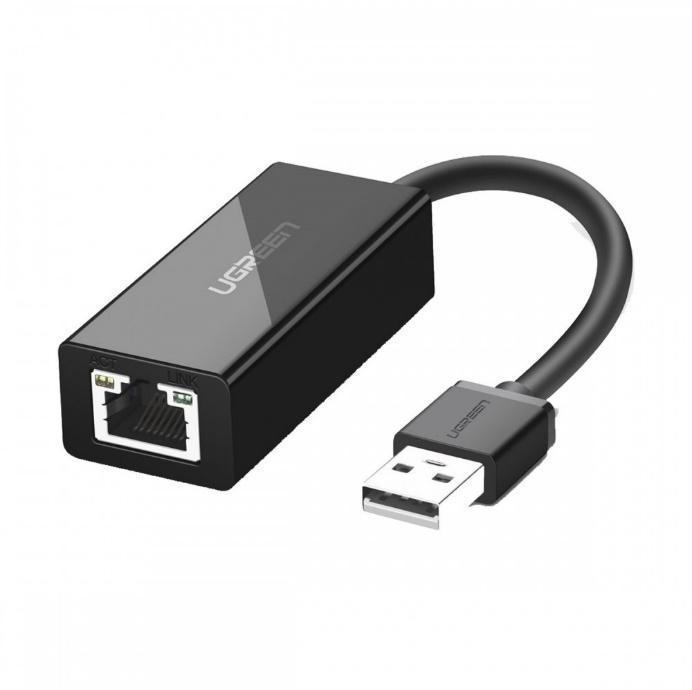
- UGreen USB Ethernet adapter
Connections
Intel DE2-115 Board
The connection between the PC and the Intel DE2-115 board is shown in the below diagram:
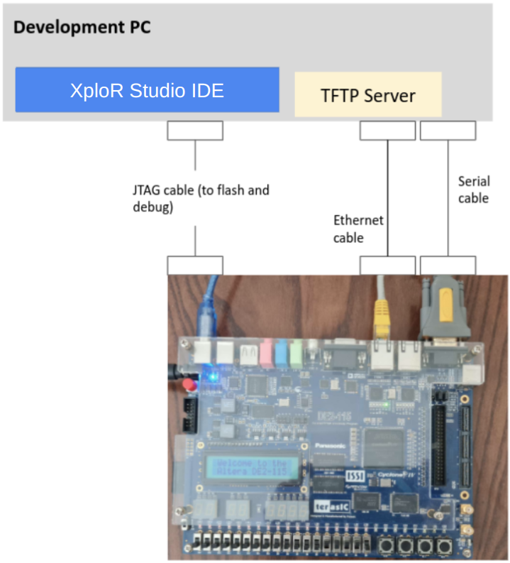
We use a single JTAG cable to flash an FPGA board and debug RISC-V IP via Virtual JTAG (vJTAG) to make things easier for the user. So please disconnect the unused FPGA board when using vJTAG.
Driver installation
On Windows
To recognize the USB blaster, drivers are needed to be installed.
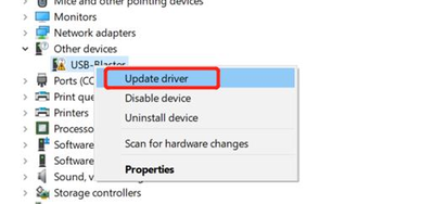
Open the Device Manager (Control Panel | Device Manager).
Right-click on the USB Blaster and then select Update driver ….
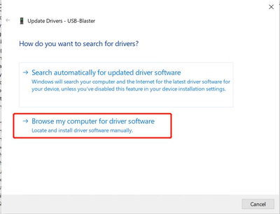
- Select Browse my computer for driver software.
- Select Browse… to select the driver you downloaded and extracted above, then click Next to install the driver.
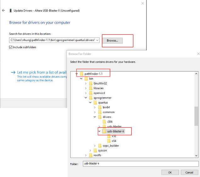
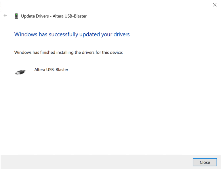
- After that, the driver should have been successfully installed.
If you see that the Altera USB Blaster II is unconfigured
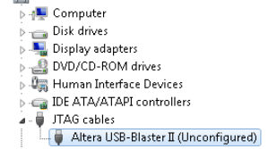
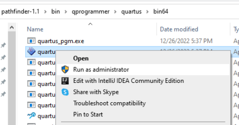
and when programming, the board cannot be detected; open Quartus programmer with administrator rights, wait a few seconds for Quartus Programmer to update the settings.
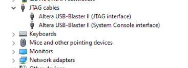
After the settings are updated, the JTAG USB can be used.
On Linux
On Ubuntu 20.04 desktop, go to path /etc/udev/rules.d/ and create rules file 51-usbblaster.rules with following content:
# USB-Blaster
SUBSYSTEM=="usb", ATTR{idVendor}=="09fb", ATTR{idProduct}=="6001", MODE="0666", GROUP="plugdev"
SUBSYSTEM=="usb", ATTR{idVendor}=="09fb", ATTR{idProduct}=="6002", MODE="0666", GROUP="plugdev"
SUBSYSTEM=="usb", ATTR{idVendor}=="09fb", ATTR{idProduct}=="6003", MODE="0666", GROUP="plugdev"

# USB-Blaster II
SUBSYSTEM=="usb", ATTR{idVendor}=="09fb", ATTR{idProduct}=="6010", MODE="0666", GROUP="plugdev"
SUBSYSTEM=="usb", ATTR{idVendor}=="09fb", ATTR{idProduct}=="6810", MODE="0666", GROUP="plugdev"
Unplug and plug USB cables.
Feedback
Was this page helpful?
Glad to hear it! Please tell us how we can improve.
Sorry to hear that. Please tell us how we can improve.